
Automatic Gauge and Interstand Tension Control (AGC/ITC)
")
System Description
The TelePro/SSE AGC system consists of a basic delay-compensating feedback control algorithm requiring only exit thickness and main motor speed measurements. Enhanced mass flow and gaugemeter control loops requiring additional process measurements, as well as feedforward control, are also included. A stand-alone roll eccentricity compensation system is available as an option. The various components of the AGC system are all fully integrated. This means that bumpless transition mechanisms are provided for changing between modes while rolling (on manual demand or automatically, due to critical sensor failure).
The ITC system for multi-stand mills consists of separate control modes for initial mill threading and steady-state rolling. The threading control mode is configured specifically to establish interstand tension during initial threading. The steady-state or run control mode is configured to reduce interactions between interstand tension and strip thickness.
The AGC/ITC functions utilize non-interactive actuator networks -- combinations of simultaneous stand speed and roll gap position (or force) changes which decouple strip thickness and tension changes. For multi-stand mills, an AGC load sharing mechanism is included to permit thickness corrections to be distributed over all available rolling stands according to a prescribed loading ratio. This load sharing mechanism reduces the amount of force variation at the final stand, thus reducing exit sheet flatness variation. Product-dependent sensitivities are computed by the mill setup models for each gauge and tension control actuator. These sensitivities determine the relative sizes and directions of the actuator movements required to make tension and gauge control corrections while reducing interactions between control loops.
The application software is implemented in the ANSI/ISO Standard C and C++ programming languages. The AGC/ITC functions are typically performed in the same PC-based computer system hardware used to implement the automatic sheet flatness control (AFC) and mill setup models.
Before a coil is processed, the AGC/ITC system receives rolling schedule information from the mill scheduling system or via manual data entry. This information includes:
- Coil identification number
- Material grade or alloy designation
- Thickness at which the material was last annealed (required if automatic calculation of control gains is desired)
- Scheduled entry, interstand, and exit thickness
- Scheduled entry, interstand, and exit tensions
- Strip width
During rolling the system receives the following process signals:
- Exit thickness deviation feedback
- Entry thickness deviation feedback (required for feedforward and mass-flow control)
- Interstand tension feedback
- Roll separating force (or HGC pressure) feedback
- Stand motor speed feedback
- Interstand and exit sheet speeds (if unavailable, these can be calculated from motor speeds, roll diameters, and nominal extrusion ratio)
- Entry sheet speed (required for mass-flow control)
Output corrections are passed to the HGC position (or pressure) and stand motor speed device controls for all rolling stands.
The AGC/ITC systems include the following functions and features:
- A delay-compensating feedback AGC algorithm that produces the fastest possible closed-loop performance in the presence of material transportation delay in the feedback measurement. Controller gains are calculated continuously to optimize response at every rolling speed.
- This algorithm consists of a Smith Linear Predictor (SLP) with internal controller parameters calculated as functions of mill speed. A conventional proportional-integral algorithm is also provided as a temporary alternative for commissioning. The primary mode of control for basic feedback AGC is the SLP configuration.
- Additional feedback AGC control algorithms based on mass-flow and gaugemeter estimates of strip thickness. A bumpless transition mechanism is provided for switching between feedback AGC modes while rolling.
- A feedforward AGC control algorithm which employs entry thickness deviation and entry sheet speed measurements to improve AGC disturbance rejection performance for incoming thickness variations.
- A thread mode tension controller specifically designed to establish interstand tensions during initial threading. The output of the thread mode controller consists of changes to stand motor speeds.
- A steady-state run mode tension controller optimized for operation once all tensions have been established. The output of the run mode controller consists of simultaneous changes to roll gaps (or HGC pressures) and stand motor speeds to permit interstand tension corrections without causing thickness changes.
- Product-dependent actuator sensitivities calculated by process models are used to adapt the AGC/ITC systems for various product grades, widths and gauges.
- AGC/ITC control functions are performed at a 20 millisecond rate in order to take advantage of high-speed actuator dynamics.
- Real-time process inputs are acquired via high-speed digital communication link or by analog interface, depending on digital link performance, sensor capabilities and customer preference. Typical digital communication links include real-time ETHERNET and reflective memory interfaces to mill drive controls.
- Outputs to the HGC position or pressure regulation and stand motor drive controls are via high-speed digital communication link or by analog interface, depending on control device capabilities, digital link performance and customer preference.
- Maintenance and diagnostic support tools are provided for monitoring the condition of key control functions. These include graphical controller monitoring displays showing the controller functional block diagrams with current values of important inputs, outputs, internal variables, and activation logic, updated in real time on the screen. Authorized personnel can modify certain system parameters on line through the screen.
- Additional system monitoring displays for actuator reference summing and product-dependent gain calculation functions.
- A high-speed, real-time trend system, including tools for displaying and/or modifying any global system variable by name through an engineering workstation. Both graphical and tabular data display are provided.
- Secure, remote access to the diagnostic support displays via standard network connection.
System Architecture
The system is implemented as a stand-alone AGC/ITC system. However, the same computer is typically used to host automatic sheet flatness control (AFC) and model setup calculations. The computing platform is the TelePro Tsentry product. It consists of an off-the-shelf Intel Pentium-class PC running the Windows 2003 Server operating system with VenturCom RTX real time extensions. This system comes complete with all facilities required to support deterministic real-time program repetition rates as fast as 1 millisecond.
In addition to performing gauge and tension control, the system includes both real-time and historical trending. Tsentry also provides a general-purpose real-time computing platform that includes all facilities and libraries required to allow the end user to develop and implement custom process monitoring, control, signal processing, and human-machine interface (HMI) applications. This system interfaces to several varieties of commercially available process I/O hardware and is capable of performing all process control and human-machine interface functions required for mill control. It was developed specifically as a high-speed real-time process control system platform.
The associated HMI displays are implemented as standard Internet web pages hosted by the Tsentry system. The standard Tsentry product includes all facilities required to develop and support a human-machine interface system based on standard web pages. These facilities include custom controls for building animated displays with Microsoft Visual Basic .NET. Automated processes are included for building web screens to execute the controls and for publishing the controls to client workstations. Any network-connected PC workstation with a standard web browser and proper security credentials can be used as an HMI client.
All hardware employs industry-standard, open-architecture systems commercially available from multiple equipment suppliers. Communication is via industry-standard TCP/IP protocol over ETHERNET. Graphical HMI/Engineering workstation displays are via standard Internet web pages allowing display using standard web browsers and screen building using standard web page development tools.
In a typical configuration, the Tsentry host computer is interfaced to RTP I/O hardware from RTP Corporation via an ETHERNET link available commercially from the I/O equipment manufacturer. Device driver software already in wide commercial use is supplied to manage the data exchange.
A fully-redundant backup CPU can be included in the architecture, but is not required. If the backup CPU is available, switchover from the primary CPU to the backup consists of simply moving network cables and re-assigning network addresses. This switchover can be performed manually in less than 15 minutes.
The automation architecture permits remote technical support through a secure ETHERNET connection. To enable remote support, the customer provides an ETHERNET LAN connection available to a trusted external site and a bridge to isolate the process control computers from the external network.
A typical hardware architecture design is shown in the following diagram:
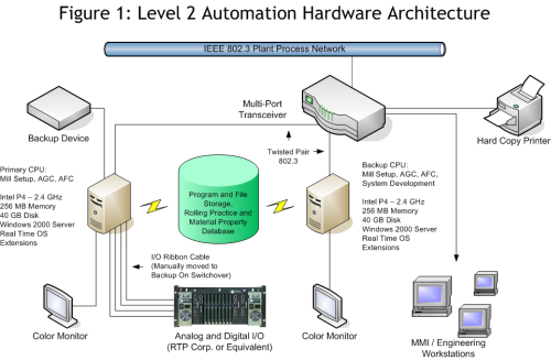
A typical Tsentry host computer is configured as follows:
- 2.4 GHz Intel Pentium 4 CPU, 512 MB memory, CDRW drive
- 60 GByte hard disks
- 2 ETHERNET controllers:
- Backplane: Intel PRO 10/100 for process LAN connection
- 3COM 3C905-TX for control I/O LAN connection
The host system is a standard IBM-compatible personal computer and can be configured according to customer requirements. Though it is not required, this can include mirrored disk configurations, PC server architectures, and alternative PC form factors.
System software includes:
- Windows 2003 Server operating system
- Microsoft Visual Studio .NET software development environment
- VenturCom RTXreal-time operating system extensions
- TelePro TSENTRY real-time process control system libraries
- Microsoft Terminal Services
- Symantec PCAnywhere
Prior to commissioning, performance tests are conducted on all systems for extended periods of time to assure reliability.
Graphical HMI/Maintenance Support Displays
Graphical HMI and maintenance support displays are implemented as standard Internet web pages hosted by the Tsentry system. Any network-connected PC workstation with a standard web browser and proper security credentials can be used as an HMI client. This permits any HMI display to be accessed from any workstation within the production complex.
Displays are developed using a combination of Microsoft Visual Basic .NET and Active Server Pages. Complete facilities for developing and publishing custom HMI displays are provided to the end user.
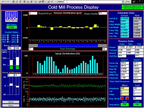
The system includes a graphical operator's display, customized for each application, showing target and actual measured exit stress distributions, work roll zone spray flow levels, entry and exit thickness deviation trend plots, roll bending and HGC tilt feedback, separating force, mill speed, and other process variables. This display is updated once per second. A sample operator's display is shown in Figure 2 below:
Figure 2: Graphical Operator's Display
In addition to the HMI display unit installed in the operator's pulpit, additional HMI workstations can be located throughout the production complex; in computer rooms, maintenance work centers, and offices. Any of these workstations can be used to display the operator's display as well as any of the controller monitoring screens.
Examples of the maintenance support displays for AGC are shown in the Figures 3 through 5. Figure 3 is the top-level feedback AGC block diagram display. Figure 4 shows the delay-compensating controller detail. Figure 5 shows the feedback AGC activation logic.
The full AGC/ITC system consists of approximately 25 HMI and system monitoring/support displays.
Figure 3: Feedback AGC: Top Level
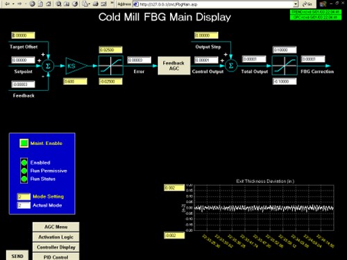
In the diagram above:
- Clicking on various portions of the diagram with a mouse device provides additional levels of detail. For example, clicking on the box marked "Feedback AGC" produces the display shown in Figure 4.
- Gain KS is a commissioning value with nominal value 1.0 which can be changed directly on the display.
- Other values displayed on yellow backgrounds are data entry as well as display fields on the screen. Security is provided to assure that only authorized personnel are permitted to make parameter changes.
- The function buttons at the lower left of the screen switch to other system displays.
- The box at the lower right of the display is a real-time variable trend plot of a critical controller variable.
Figure 4: Feedback AGC Controller
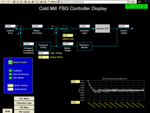
In the diagram above:
- Clicking on the box marked "Monitor PID" displays additional levels of algorithm detail.
- The box at the lower right of the display is a real-time variable trend plot of a critical controller variable.
Figure 5: Feedback AGC Activation Logic
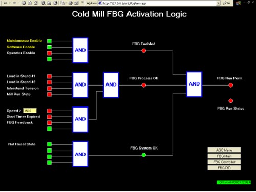
In the diagram above:
- True states are indicated by filling the associated box (for inputs) or circle (for outputs) with green. False states are indicated with red.
- The state of the maintenance enable logical can be changed by clicking with a mouse device directly on the state indicator.
Real-Time/Historical Trend Facility
The Tsentry computing platform provides a real-time/historical data trend facility which supports Internet web page based editing and display of process variables. Data may be displayed and edited from a browser run on the system console or on any network-connected Windowsworkstation. Both graphical and tabular data displays are provided.
The real-time/historical trend system includes the following functions and features:
- Access by name to any process variable in host global shared memory by means of a data dictionary.
- Data dictionary build process. This process automatically updates the global shared memory data dictionary when new variables are added to the system and old ones are deleted.
- Real-time trend data acquisition. Data is acquired at a 20-millisecond rate (50 samples per second per point) and made available for display on networked HMI/maintenance support workstations.
- Real-time trend data display. Web page screens are provided for graphical and tabular display of high-speed, real-time data.
- Display pan and zoom features.
- Trend data can be exported as individual Windows files.
- Storage, retrieval, and editing of trend set files, which define graphical and tabular data display configurations: variable names, scaling, display attributes.
- Dynamic trend display editing allows interactive modification of trended variable names, time scales, signal magnitude scales, and text display formats.
- Historical trend display integrated with real-time trend displays.
- Facilities for starting and stopping historical trend data acquisition based on user-defined trigger events.
- Support for multiple variable types: floats, integers, character strings, Booleans.
- Multiple value display formats: float, character, decimal integer, hexadecimal integer, and binary.
- Process variable "Probe" screen. A web page is provided for displaying and modifying any process variable in shared memory by name. The screen is accessible from a web browser run on the system console or on any networked Windows workstation. Data write access can be password protected.
- Process variable "ProbeA" screen. Same functionality as "Probe" for multidimensional array data objects.
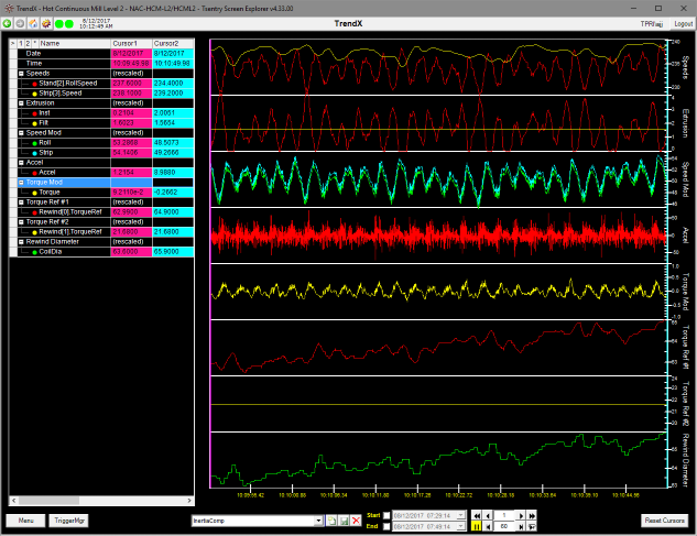
- Process variable "TrendX" screen. View up to 24 simultaneous signal trends in real time on up to six independent Y axes.
Examples of the Probe and TrendX screens are shown in the Figures 6 and 7.
Figure 6: Process Variable "Probe" Screen
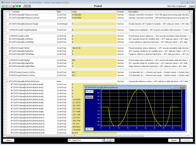
Figure 7: Process Variable "TRENDX" Screen
Conclusion
This system consists of standard TelePro/SSE rolling process control technology tailored to the specific needs of each customer. The use of proven automation products improves system reliability and reduces the time required for engineering, development, installation and commissioning. These standard products are customized for each application in the areas of: system sequencing, operator interface requirements, maintenance and diagnostic support tools, mill-specific equipment interfaces, and the plant scheduling interface. The use of standard, open-architecture system components allows for configuration flexibility and eliminates special-purpose hardware/software.
TelePro/SSE mill automation systems are designed, developed, commissioned and supported by engineers with extensive process control experience on all types of rolling mills. We have spent many years working directly with plant technical and operating personnel to understand the functional requirements for these systems. Our process understanding and system integration expertise make us uniquely qualified to deliver the highest levels of performance and reliability across a wide range of product and process conditions.